Build your own Operating System #5
Interrupts and Input
Hello everyone!
This is the fifth article of the “Build your own Operating System“ article series. First of all, I like to suggest, please refer to previous articles, before reading this. It will help you to better understanding of this article.
Now that the OS can produce output it would be nice if it also could get some input. Refer below article to know about how to display text on the console as well as writing data to the serial port.
The operating system must be able to handle interrupts in order to read information from the keyboard. An interrupt occurs when a hardware device, such as the keyboard, the serial port, or the timer, signals the CPU that the state of the device has changed. The CPU itself can also send interrupts due to program errors, for example when a program references memory it doesn’t have access to, or when a program divides a number by zero.
What Does Software Interrupt Mean?

A software interrupt is a type of interrupt that is caused either by a special instruction in the instruction set or by an exceptional condition in the processor itself. A software interrupt is invoked by software, unlike a hardware interrupt, and is considered one of the ways to communicate with the kernel or to invoke system calls, especially during error or exception handling.
A software interrupt often occurs when an application software terminates or when it requests the operating system for some service. This is quite unlike a hardware interrupt, which occurs at the hardware level. A software interrupt only communicates with the kernel and indirectly interrupts the central processing unit. All software interrupts are associated with an interrupt handler, which is actually just a routine that is activated when an interrupt happens. Only one bit of information is communicated during a software interrupt. Often, a software interrupt is used to perform an input/output request. This request, in turn, calls kernel routines that actually perform the service.
A software interrupt often emulates most of the features of a hardware interrupt. Like a hardware interrupt, it calls only a specific interrupt vector and saves the accumulators and registers. A software interrupt can also make use of some of the hardware interrupt routines.
Similar in functionality to a subroutine call, a software interrupt is used for different purposes in a device. One notable example is when communicating with the disk controller for reading and writing data to and from a disk.
Interrupts Handlers
Interrupts are handled via the Interrupt Descriptor Table (IDT). The IDT describes a handler for each interrupt. The interrupts are numbered (0–255) and the handler for interrupt i is defined at the ith position in the table. There are three different kinds of handlers for interrupts:
·Task handler
· Interrupt handler
· Trap handler
The task handlers use functionality specific to the Intel version of x86, See the Intel manual, chapter 6, for more info. The only difference between an interrupt handler and a trap handler is that the interrupt handler disables interrupts, which means you cannot get an interrupt while at the same time handling an interrupt. In this article series, we will use trap handlers and disable interrupts manually when we need to.
Interrupt Descriptor Table
Interrupt descriptor table (IDT) is an x86 system table that holds descriptors for interrupt handlers (The IDT describes an interrupt handler for each interrupt). The IDT is used by the processor to determine the correct response to interrupts and exceptions. IDT have 256 entries where the interrupts are numbered from 0 to 255. The handler for interrupt i is defined at the ith position in the table.
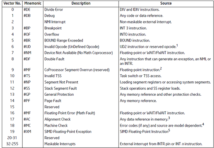
Interrupt Descriptor Table is similar to the Global Descriptor Table we discussed in the previous article in structure. Before you implementing the IDT, always make sure you have a working GDT.
To know more about IDT read the below article.
Creating an Entry in the IDT
An entry in the IDT for an interrupt handler consists of 64 bits. The highest 32 bits are shown in the figure below:
Bit: | 31 … 16 | 15| 14 13|12 | 11 |10 9 8 |7 6 5 |4 3 2 1 0|Content:| offset high | P | DPL | 0 | D | 1 1 0 | 0 0 0| reserved|
The lowest 32 bits are presented in the following figure:
Bit: | 31 ……… 16 | 15 ……… 0 |Content: | segment selector | offset low |
A description for each name can be found in the table below:
Name Descriptionoffset high The 16 highest bits of the 32 bit address in the segment.offset low The 16 lowest bits of the 32 bits address in the segment. p If the handler is present in memory or not (1 = present, 0 = not present). DPL Descriptor Privilige Level, the privilege level the handler can be called from (0, 1, 2, 3). D Size of gate, (1 = 32 bits, 0 = 16 bits).segment selector The offset in the GDT. r Reserved.
The offset is a pointer to code (preferably an assembly code label). For an instance, to create an entry for a handler whose code starts at 0xDEADBEEF and that runs in privilege level 0 (therefore using the same code segment selector as the kernel) the following two bytes would be used:
0xDEAD8E000x0008BEEF
If the IDT is represented as an unsigned integer idt[512] then to register the above example as an handler for interrupt 0 (divide-by-zero), the following code would be used:
idt[0] = 0xDEAD8E00idt[1] = 0x0008BEEF
In this method each and every interrupt can be identify with it’s unique number. This is known as IRQ number or interrupt request number. For your more information about IRQ numbers refer the following table here.
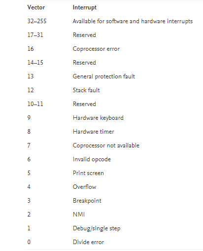
After the CPU finds the entry for the interrupt, it jumps to the code that entry points to. Then that code is run in response to the interrupt is known as a interrupt service routine (ISR) or an interrupt handler.
Handling an Interrupt
When an interrupt occurs there are three main steps that has to complete by the system.
1. Save the current state of the process
2. Handle the interrupt
3. Restore the CPU process and execute it
When an interrupt occurs the CPU will push some information about the interrupt onto the stack, then look up the appropriate interrupt hander in the IDT and jump to it. The stack at the time of the interrupt will look like the following:
[esp + 12] eflags[esp + 8] cs[esp + 4] eip[esp] error code?
The reason for the question mark behind error code is that not all interrupts create an error code. The specific CPU interrupts that put an error code on the stack are 8, 10, 11, 12, 13, 14 and 17. The error code can be used by the interrupt handler to get more information on what has happened. Also, note that the interrupt number is not pushed onto the stack. We can only determine what interrupt has occurred by knowing what code is executing — if the handler registered for interrupt 17 is executing, then interrupt 17 has occurred.
Once the interrupt handler is done, it uses the iret instruction to return. The instruction iret expects the stack to be the same as at the time of the interrupt (see the figure above). Therefore, any values pushed onto the stack by the interrupt handler must be popped. Before returning, iret restores eflags by popping the value from the stack and then finally jumps to cs:eip as specified by the values on the stack.
The interrupt handler has to be written in assembly code, since all registers that the interrupt handlers use must be preserved by pushing them onto the stack. This is because the code that was interrupted doesn’t know about the interrupt and will therefore expect that its registers stay the same.
But since writing them all in assembly code will be tedious. So let’s do this on C language. So let’s creating a handler in assembly code that saves the registers, calls a C function, restores the registers and finally executes iret code.
The interrupt handler written in C language should get the state of the registers(struct cpu_state and struct stack_state) the state of the stack and the number of the interrupt as arguments. The following definitions can for example be used:
struct cpu_state { unsigned int eax; unsigned int ebx; unsigned int ecx; . . . unsigned int esp;} __attribute__((packed));struct stack_state { unsigned int error_code; unsigned int eip; unsigned int cs; unsigned int eflags;} __attribute__((packed));void interrupt_handler(struct cpu_state cpu, struct stack_state stack, unsigned int interrupt);
These codes creates a background for executing the interrupt. Now let’s jump in to the part of coding the interrupt handler which actually execute the interrupt.
Creating a Generic Interrupt Handler
Since the CPU does not push the interrupt number on the stack it is a little tricky to write a generic interrupt handler. Here will use macros to show how it can be done. Writing one version for each interrupt is tedious — it is better to use the macro functionality of NASM. And since not all interrupts produce an error code the value 0 will be added as the “error code” for interrupts without an error code. The following code shows an example of how this can be done:
The common_interrupt_handler does the following:
· Push the registers on the stack.
· Call the C function interrupt_handler.
· Pop the registers from the stack.
· Add 8 to esp (because of the error code and the interrupt number pushed earlier).
· Execute iret to return to the interrupted code.
Since the macros declare global labels the addresses of the interrupt handlers can be accessed from C or assembly code when creating the IDT.
Loading the IDT
The IDT is loaded with the lidt assembly code instruction which takes the address of the first element in the table. It is easiest to wrap this instruction and use it from C. To do this create idt.s file on your working directory and write the given code to it.
Programmable Interrupt Controller (PIC)
A Programmable Interrupt Controller (PIC) is a interrupt controller that manages interrupt signals received from devices by combining multiple interrupts into a single interrupt output. PIC is found on most PCs today. One of the most well-known Programmable Interrupt Controllers is Intel 8259A, which was included in the x86 PC as a part of the motherboard chipset.
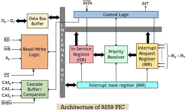
Before start using hardware interrupts you must configure the Programmable Interrupt Controller (PIC). The PIC makes it possible to map signals from the hardware to interrupts. The reasons for configuring the PIC are:
· Remap the interrupts. The PIC uses interrupts 0–15 for hardware interrupts by default, which conflicts with the CPU interrupts. Therefore the PIC interrupts must be remapped to another interval.
· Select which interrupts to receive. You probably don’t want to receive interrupts from all devices since you don’t have code that handles these interrupts anyway.
· Set up the correct mode for the PIC.
In the beginning there was only one PIC (PIC 1) and eight interrupts. As more hardware were added, 8 interrupts were too few. The solution chosen was to chain on another PIC (PIC 2) on the first PIC (see interrupt 2 on PIC 1).
The hardware interrupts are shown in the table below:

Every interrupt from the PIC has to be acknowledged — that is, sending a message to the PIC confirming that the interrupt has been handled. If this isn’t done the PIC won’t generate any more interrupts.
Acknowledging a PIC interrupt is done by sending the byte 0x20 to the PIC that raised the interrupt.
To Implementing a pic_acknowledge function create pic.h header file and pic.c file on your working directory. Codes are given below.
Reading Input from the Keyboard
The keyboard does not generate ASCII characters, it generates scan codes. A scan code represents a button — both presses and releases. The scan code representing the just pressed button can be read from the keyboard’s data I/O port which has address 0x60.
To do this create keyboard.c file with the given code on your working directory.
#include “io.h”#define KEYBOARD_DATA_PORT 0x60/** read_scan_code:* Reads a scan code from the keyboard** @return The scan code (NOT an ASCII character!)*/unsigned char keyboard_read_scan_code(void){ return inb(KEYBOARD_DATA_PORT);}
The next step is to write a function that translates a scan code to the corresponding ASCII character. Below gave the full code for keyboard.c file and also make sure to include keyboard.h header file for fulfilling this.
Update your kmain.c file like this.
Finally, update OBJECTS variable of Makefile as shown in the figure below:
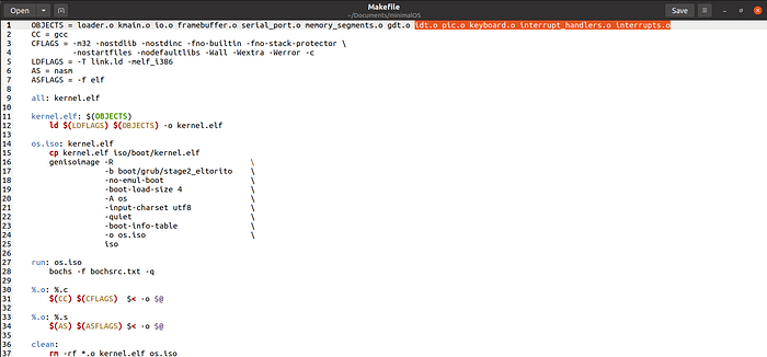
Remember, since the keyboard interrupt is raised by the PIC, you must call pic_acknowledge at the end of the keyboard interrupt handler. Also, the keyboard will not send you any more interrupts until you read the scan code from the keyboard.
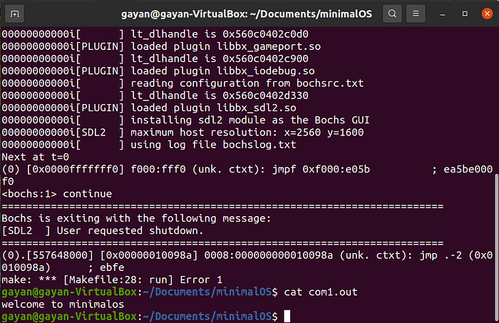
You can check your result by cat com1.out command. This com1.out file will contain whatever you type on your keyboard.
Congratulations! now you know to get input in the console and handling interrupts. In the next article, I’ll talk about “User Mode”. Thank you so much for reading!
References:
The Little OS Book: https://littleosbook.github.io/book.pdf
